 EvaporativeCooler:Indirect:WetCoil
Used in:
- Air Handling Units
|
|
|
Used in:
|
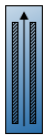
The wetted coil evaporative cooler shown in the figure below, has water sprayed directly on the tubes of the heat exchanger where latent cooling takes place. The vaporization of the water on the outside of the heat exchanger tubes allows the simultaneous heat and mass transfer which removes heat from the supply air on the tube side. Secondary air at ambient conditions is passed over the wet coil and is exhausted to outside. The secondary air stream has its own fan.

Evaporative Cooler – Indirect Wet Coil
The process that the secondary air goes through, A to C on the following figure, is a path of simultaneous heat and mass transfer, but it does not follow a line of constant enthalpy as in the direct stage. The process is not adiabatic due to the heat gain from the supply air flowing through the tubes of the heat exchanger.
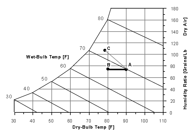
Secondary Air Process – Indirect Wet Coil Evaporative Cooler
A unique name for an instance of an evaporative cooler which is predetermined by DesignBuilder.
Select the type of evaporative cooler from the list of options:
The maximum efficiency of the stage is a combination of the efficiency due to the simultaneous heat and mass transfer on the outside of the tube and the efficiency of the heat exchanger. This value can be higher than the dry coil overall efficiency since the convective coefficients on the outside of the tube are larger.
The Coil flow ratio is determined from performance data. The Coil Flow Ratio tells how quickly the efficiency of the stage would decrease with a mismatch of the supply and secondary flows.
This field is optional and can be used to model additional water consumed by the cooler from drift. Drift is water that leaves the cooling media as droplets and does not evaporate into the process air stream. For example, water may get blown off the evaporative media by winds and escape the air system. The value entered here is a simple fraction of the water consumed by the cooler for normal process evaporation. The amount of drift is this fraction times the water evaporated for the normal cooling process. This field can be left blank and then there will be no added water consumption from drift.
This field is used to specify the effectiveness of the indirect heat exchanger between the primary and secondary air flow.
This field is used to specify the power consumed by the water pump that circulates water (in W).
This field is used to specify the secondary fan flow rate and is specified in m3/s or ft3/min.
This field is used to specify the total efficiency of the fan and is used to calculate the power consumed by the evaporative cooler secondary fan. Input values should be between 0 and 1.
This field is used to specify the delta pressure across the secondary stage of the evaporative cooler (in Pa or in H2O).
Select this option to model additional water consumed by the cooler from blowdown. Blowdown is water that is intentionally drained from the cooler’s sump to offset the build up of solids in the water that would otherwise occur because of evaporation.
The value entered here is dimensionless. It can be characterized as the ratio of solids in the blowdown water to solids in the make up water. Typical values are 3 to 5. The default is 3.0.
Schedule that defines when the coil is available, i.e. whether the evaporative cooler can run during a given time period. A schedule value greater than 0 (usually 1 is used) indicates that the unit can be on during a given time period. A value less than or equal to 0 (usually 0 is used) denotes that the unit is off.